Click on any image to start a slideshow. Click the Pause symbol in the upper right corner to stop at an image.
This “batch” chassis fabrication was originally written in 2015 and updated in 2022. There are several examples of one-off constructions documented in the Restorations section of this website.
New chassis are needed for two +4 projects currently in work. Those available in the US are fabricated of square tube rather than the formed hat-sections of the originals made by Rubery-Owen for Morgan. There are other differences as well so the only option for acquiring an original specification chassis is to make it.
Detailed CAD models and drawings were made using existing chassis for reference.
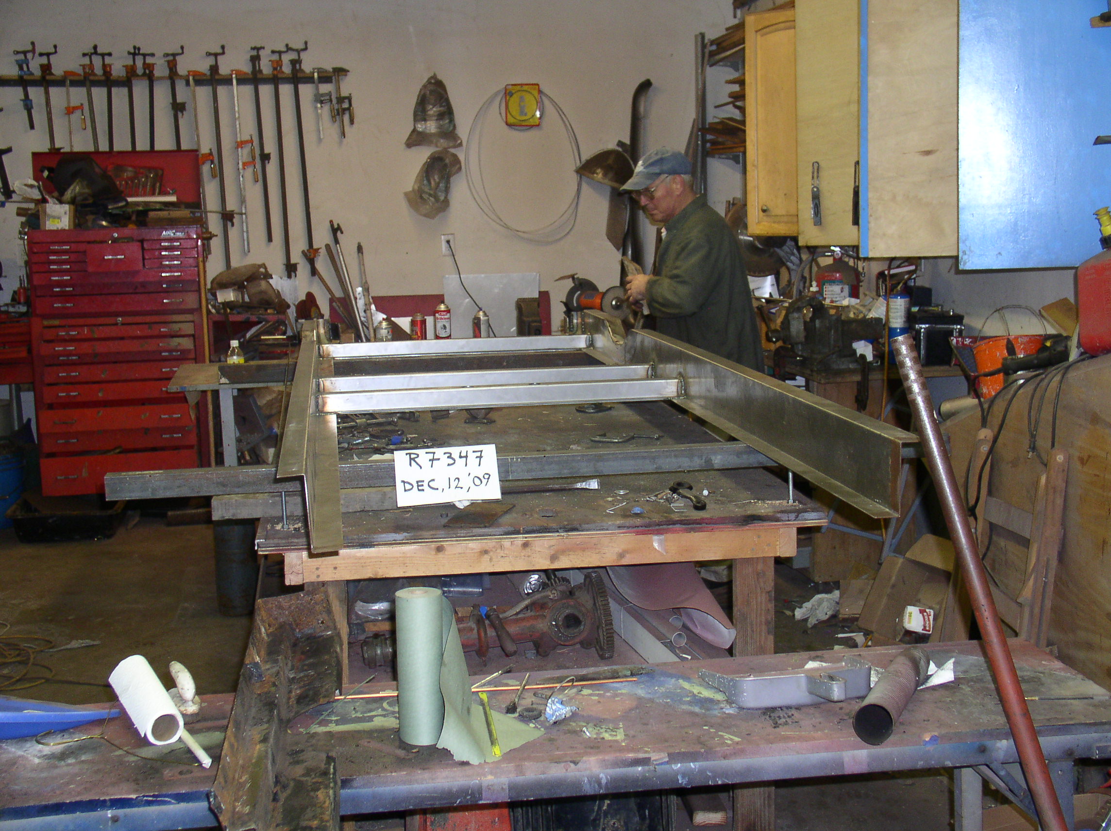
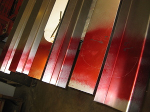
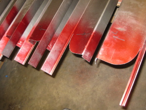
 The basic stampings were made to the drawings by a local sheet metal fabricator. Due to the complexity of the parts and the low volume (high cost) only the shear and break operations were done by the fabricator. Additional consideration was given to efficient material usage and minimizing machine set-ups to make the project economically reasonable. Material for five chassis offered the best cost per unit compromise .
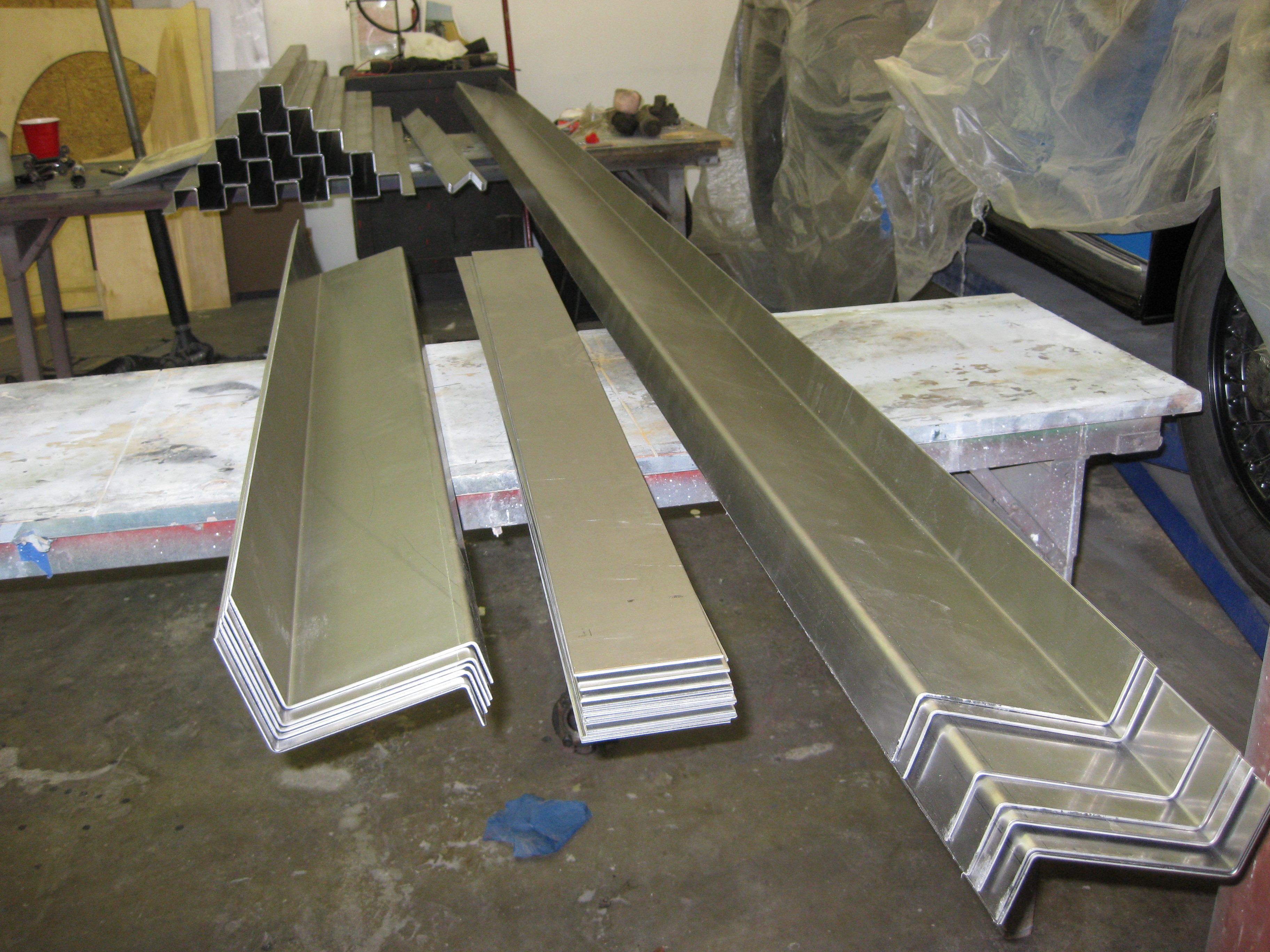
Having the flanges added to the ends of the crossmembers by the fabricator made the out-of-pocket cost prohibitive. As always there is a trade off between what I am willing to spend to have work done by others and what I will tolerate doing myself. In this case I chose do to the grunt work.
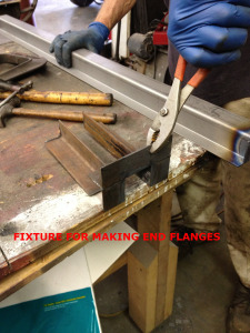
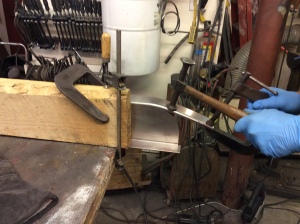
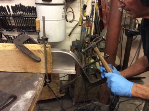
The end of each hat-section is notched and slit with a saw. A steel fixture is clamped to the hat-section and acts as an anvil so repeatable flanges can be made on three sides using oxy-acetylene heat and a hammer.
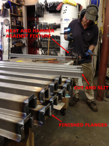

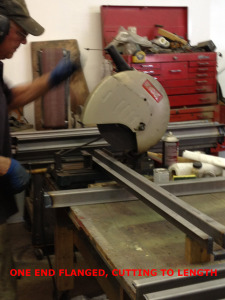
After forming the flanges on one end the hat-sections are cut to length for flanging the opposite end.
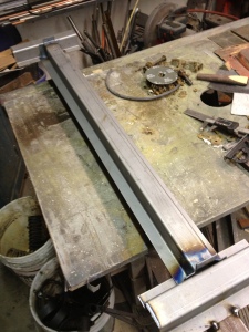
The flanging fixture is modified to assure accurate finished length and a go-no go gauge is used to verify the final size of each crossmember after flanging.

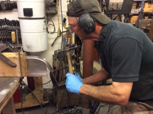
The aft and second to last crossmember have angle brackets to attach the springs. If you wanted to make thousands of them the cost would be negligible. The quotes I got for just ten of each convinced me to make them myself. The fixture for bending the spring brackets is a half-inch thick steel plate with an angle iron fence welded to it. The bracket bend-length is established with a vernier caliper and the bend made by heating and hammering. The drilling fixture is simply a few pieces of scrap steel clamped to the base of the drill press.
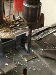

First pass is with a center-drill for the pilot hole on all the pieces and that is followed by the correct finish hole size drill. Despite the seemingly crude blacksmithing approach the finished parts are remarkably consistent. The brackets are welded to the crossmembers.
The second crossmember from the front has the jacking points and the holes for the transmission mounts. To get the correct internal diameter and the correct wall thickness I had a choice. I could buy four feet of tube, roughly double the amount required, for about $40 or 22′ for $70. I have a lot of tubing left over.


The front crossmember is the most challenging. The original has two short flanges on the outside vertical edges and complex coping to fit the side rails. The finished width is critical, too small and the firewall buckles, too large and side of the firewall is pulled outboard causing the rear of the wings to flare. For this task I resorted to a saber saw and tediously followed the pattern lines.


A full length clamping fixture and oxy/act heat made repeatable flanges on the ends (greater than 90°) to match the curve of the side rails.
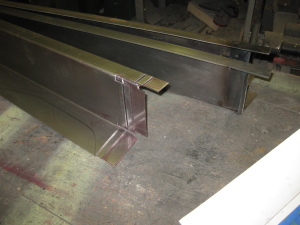
I tried several methods for making the bend in the long side rails. Eventually I settled on a process where I welded the three rear crossmembers to the rails and using an oxy/acetylene torch, a tape measure and pattern heated the Z sections and formed the bend by eye.

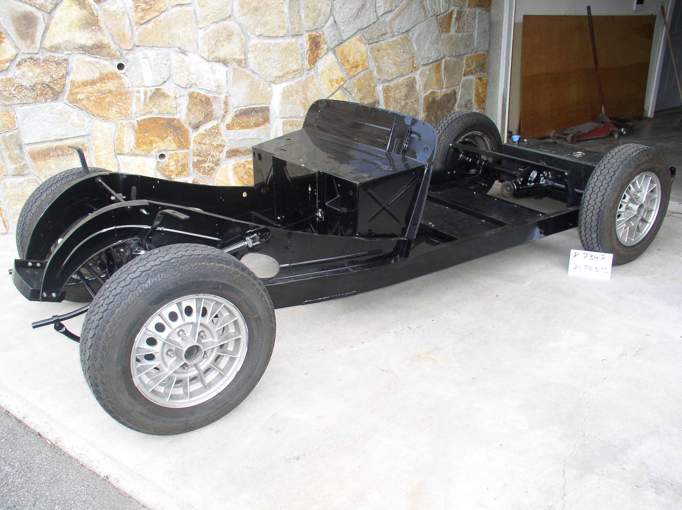
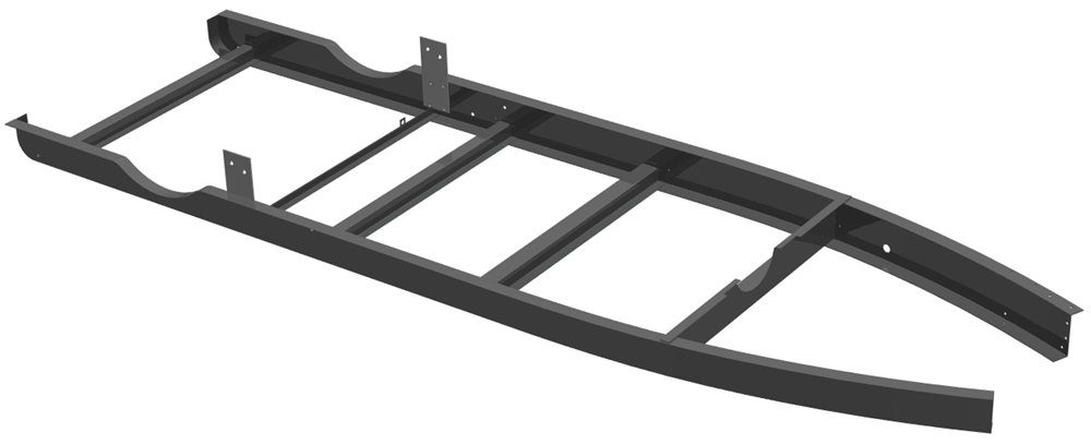
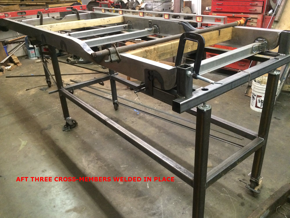
With the crossmembers pretty much complete it is time to move on to the side rails. The top flange is slightly smaller than the bottom flange so marking each as a left or a right side part is an important first step. The final assembly of the crossmembers and side rails will be done on a fixture to assure repeatable measurements and alignment. The axle cutouts and rear turn-ups can be done before or after the crossmembers are welded in. Having a fixture makes it preferable to complete these features before assembly.
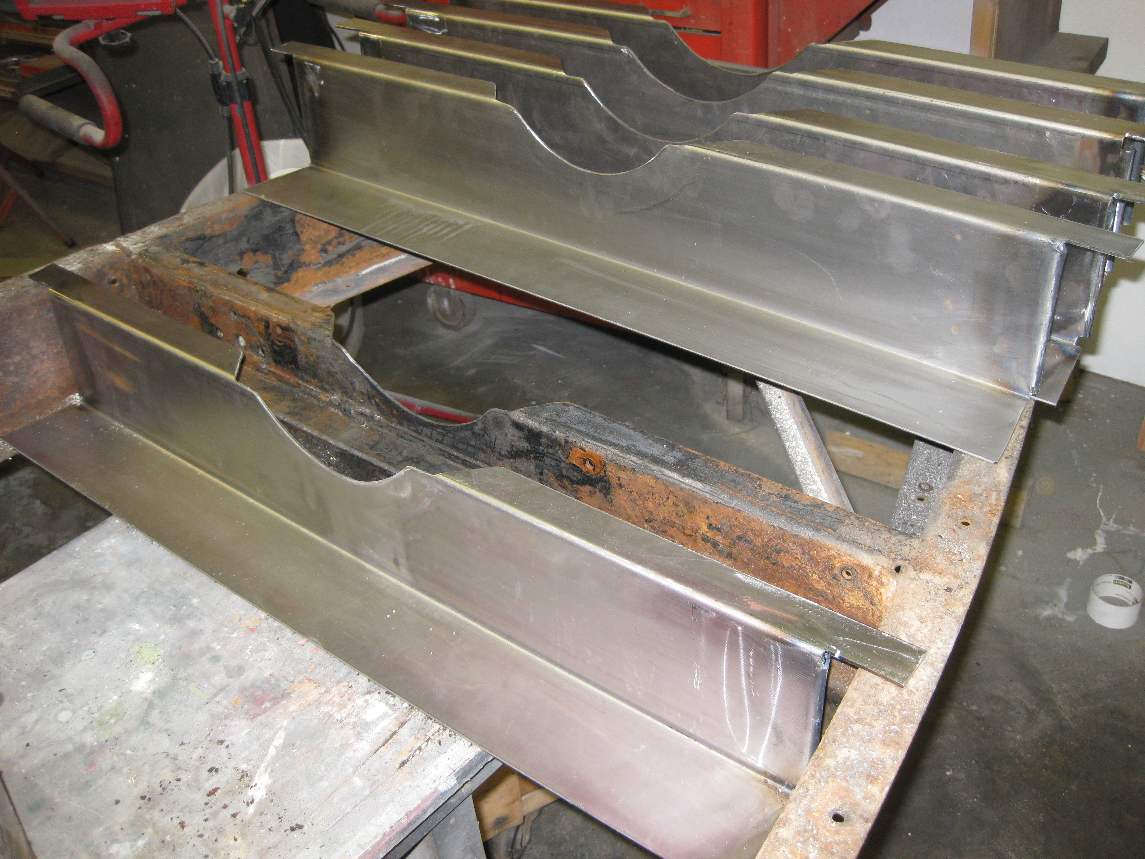
The original rails were formed on a press and the flange bend radii are smooth and continuous around the axel cutout and turn-up. Note how the cuts for these features is made at the tangent point of the flange radius. After cold forming the bend using a big C-clamp as a handle/lever and tapping with a body hammer the seam is welded and ground duplicating the appearance of the original.

To make the axel cutout with continuous radii like the rear turn-up I used a saber-saw to cut along the break line of the flange and pattern lines drawn on the metal. the flange portion has to be formed to follow the cutout much the same way as the rear turn-up but because of the complexity of the bend it must be done with Oxy/Act rather than being bent cold. The two rail bottom flanges are clamped together with a small spacer between them. From experience I learned the rails bend because all the welding is on one side. Clamping the spacer between the bottom flanges and heating the web of the rail “pre-bends” it as compensation.The first bend of the top flange is up and away from the rail. When the first bend has cooled a bit the aft part of the flange is heated and pushed into contact with the rest of the cutout. A few clamps keep the web and the flange in line for a row of tack welds.


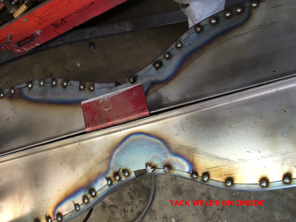

the rails, still clamped together, are turned over. A weld prep (groove) is cut along the joint using a cut-off blade on the 4″ grinder. The joint is then MIG welded. A filler piece is fabricated and welded in place to close the center opening. The welds are ground flush before the rails get turned back to the tack welded side. The tack welds are ground flush, a weld prep cut and MIG welded before finish grinding. When completed the weld joint should be near invisible and the cutout fair and smooth (just like stamped).
Bending rails: I work alone so holding a torch, a hammer, a dolly AND a camera just is not possible. A mostly verbal description will have to suffice. Starting with what you already know: Steel is malleable when red hot. It can stretch and it can also shrink. To stretch it simply heat to red and pull. For the chassis, bar clamps at the front provide the pull. Starting about 8″ aft of the front crossmember heat a 4″ section of the flange red in a more or less diagonal pattern. The preload on the clamps will cause it to stretch/bend. Move forward and heat an overlapping patch and bend some more. Bending must be gradual. It is easier to add bend than it is to remove over-bend. Now go to the lower flange and heat the equivalent area. When it is red hot give it a whack with a hammer to dimple it down; just a little. Move forward about 4″ more and repeat. Keep repeating the process top/bottom until the “targets” (cross member with the pedal set and the front sub frame and engine mount location) are matched. The KEY is to go slow and bend uniformly, no kinks or corners; a “fair curve”.
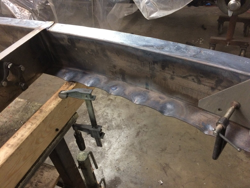

After both sides are bent and the front subframe clamped in place and the pedal crossmember tack welded and everything is square and true: Heat one of the bumps on the lower flange red again and bang it up with a dolly (a heavyish chunk of steel used by body techs) and hammer it flat while hot. It will shrink flat. Repeat on all the bumps. The hammering is not hard. Aside from the first bang up with the dolly the hammering is more bouncing the hammer all around the hot area. Stop tapping when it is black again. Reheat and repeat if necessary. Depending on your skill and how much time you want to take you can make it pretty much perfect (or not).
To repeat: Heating expands and softens steel. Hammering while hot makes the molecules pack closer together so when the steel cools it is a bit smaller (shrink).
This section was originally written in 2015. It is now 2022. Several more Morgan restorations have passed through the shop in that time. Many examples of ONE-OFF chassis builds can be found in the Restorations section of the website. Some predate this article others followed. It is a lot of work and dimensions are critical. In hind sight, if I knew 50 years ago, when I bought my first Morgan that I would still be banging steel at age 76 I would have taken up bowling instead.
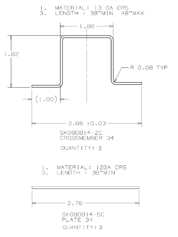
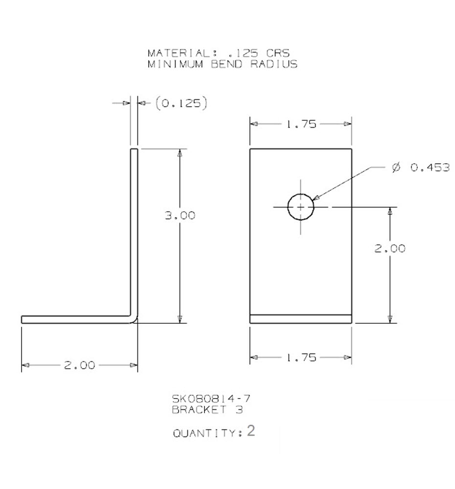
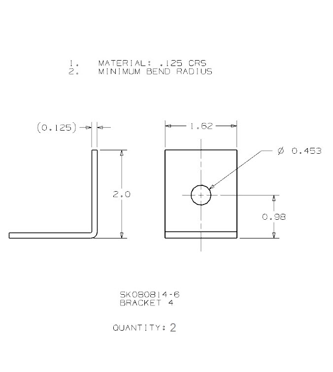
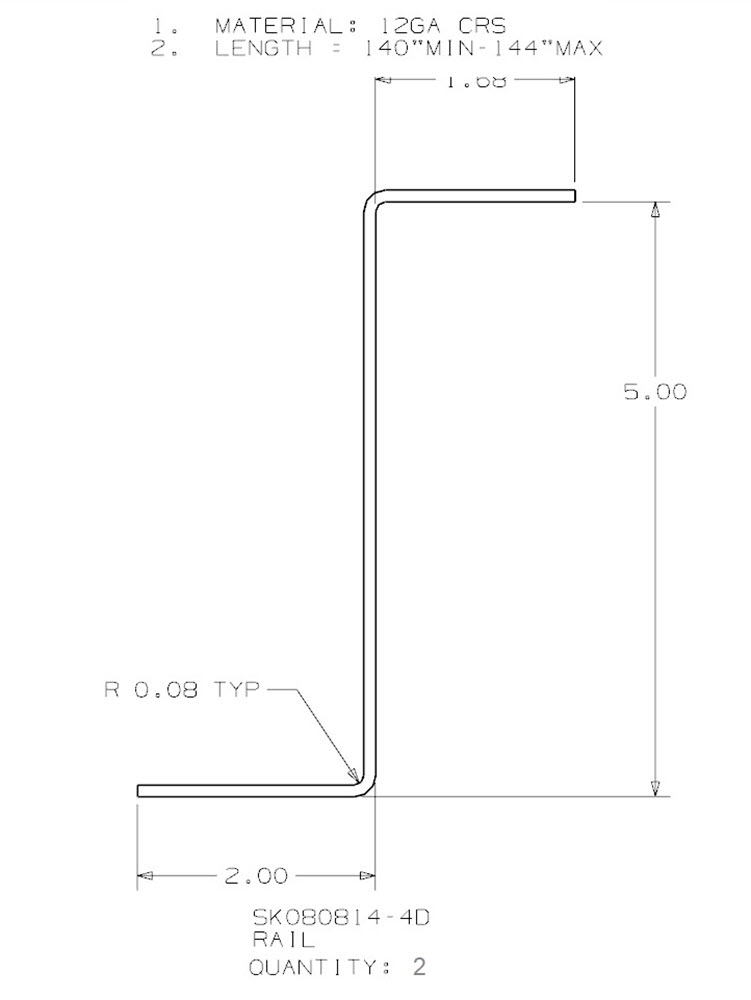
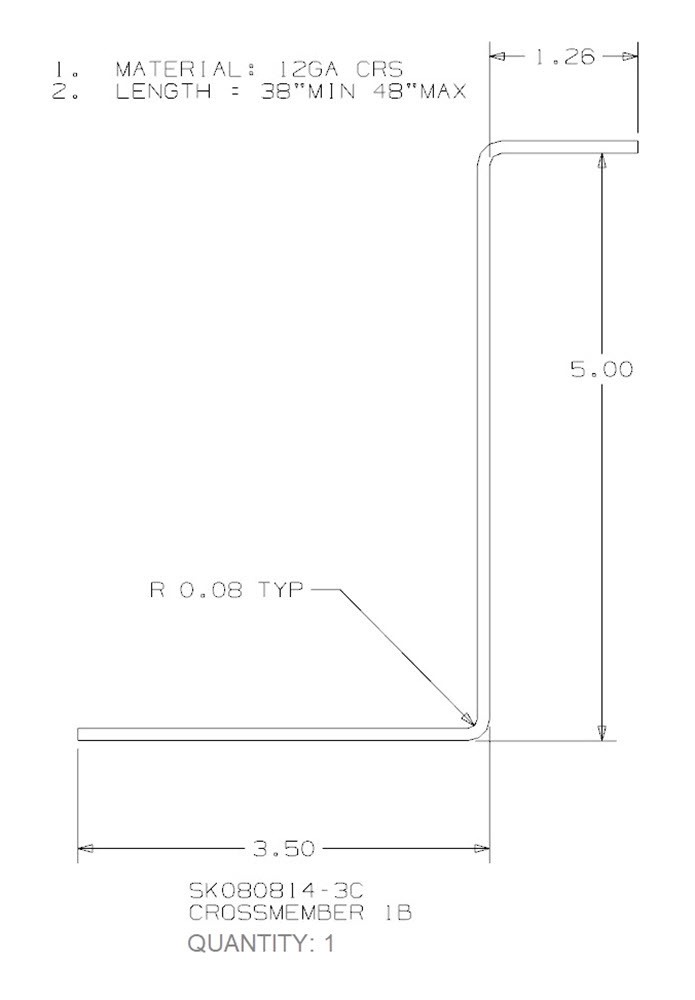
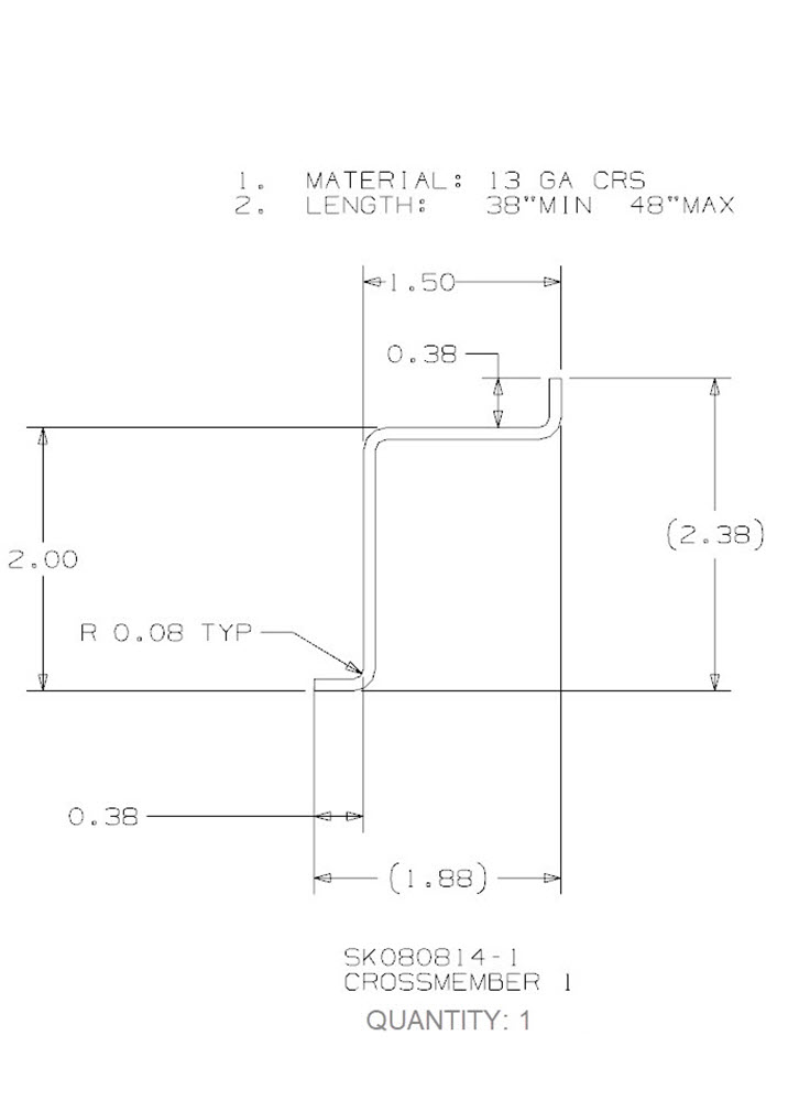
The following drawings are provided for reference only. User assumes all responsibility.