Applies to Morgans with chassis mounted gas tanks; late ’50 through the ’60s
I have often heard the bellcrank/compensator linkage for the handbrake on early Morgans with chassis mounted petrol tanks referred to as a “Harpoon”. There have been several cases of these cars bursting into flames when struck from behind by another car. It takes little imagination to visualize the petrol tank being pushed forward, only an inch or so, to be punctured by the handbrake bellcrank.
A few years ago I saw Lorne Goldman’s burned out +8 passing on a flatbed. I designed replacement linkage at the time but didn’t get to build it until much later for my 1964 +4 four seater. It consists of telescoping stainless steel rods and tube with the brake cable attached directly. The cable is arraigned such that it pulls the opposing rods together engaging the rear brakes. As of this writing the system has been in the car for three years and works perfectly. I designed it solely for safety purposes but it operates better than the compensator it replaced. I assume that is because there are fewer pivots and points where wear and slop can reduce effectiveness but, then again, maybe it is only the inventor’s imagination.
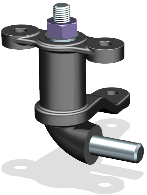
Original Linkage with Telescoping Tube

The functioning should be pretty obvious. The cable anchored with an adjuster in the left rod pulls on the right rod moving both rods equally and actuating the brakes. As mentioned it has been in service for some time now and has worked well. I redesigned it for two reasons. First; I was concerned that in time crud (or ice) could collect in the telescoping tube and inhibit the operation. Second: I thought the design could be simplified to eliminate the tubing and also the threading operation on the rod ends.
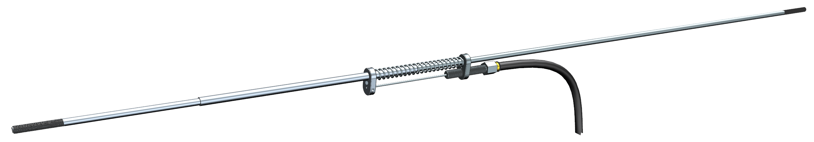
Revised Linkage with Parallel Rods
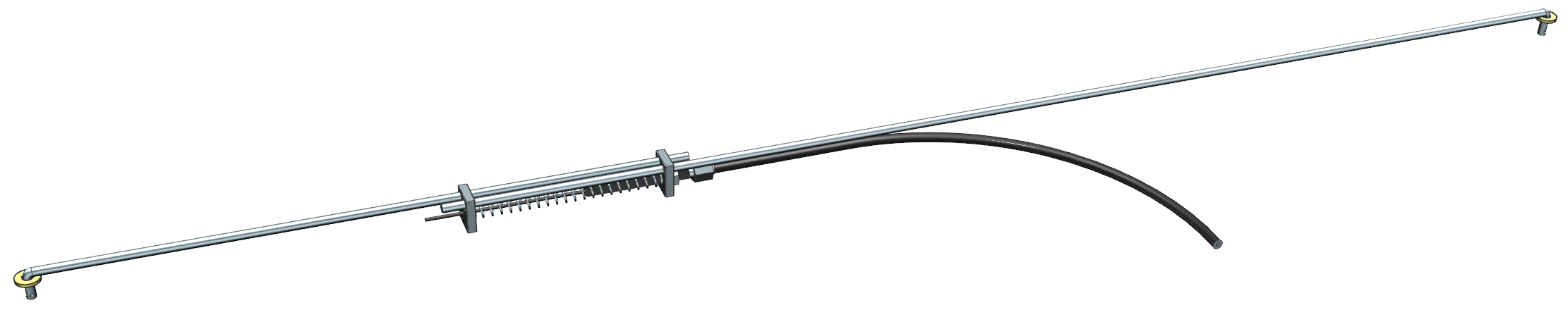

Close up of center section:

Functioning is exactly the same but with parallel rods rather than telescoping. Also bent ends replace the threads and clevises.
And this is how it looks installed:

When you are satisfied that it is working satisfatorily saw the bellcrank mount off of the axel housing.
I have installed the second version in three cars now and am satisfied that it works as planned and provides an additional margin of safety
And now the disclaimer:
This is provided for informational purposes only. Anyone that copies or otherwise adapts this information assumes all responsibility. The author is not recommending or advising any implementation.
Detail Drawings

Making the anchors:
All material is 304 or 316 Stainless Steel.
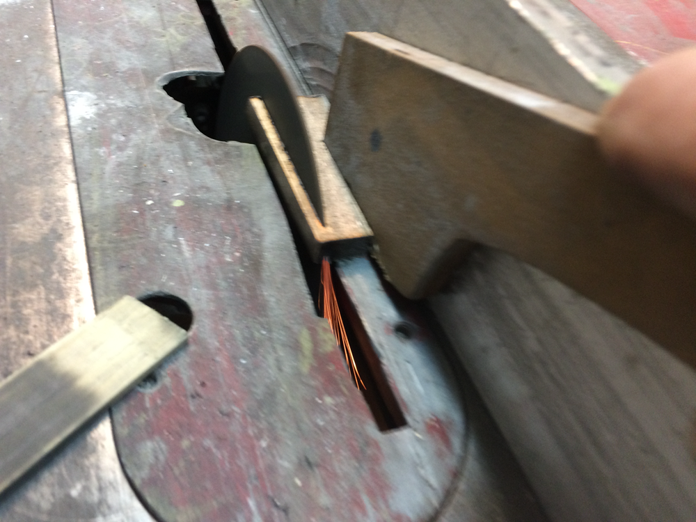
- SS bar is cut to size on a table saw with abrasive cut-off blade. Safety glasses and an abundance of caution is required:
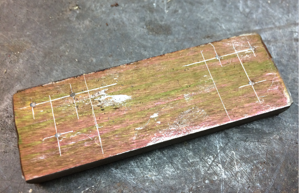
2. Color bar with dye to make marking easier and layout holes.
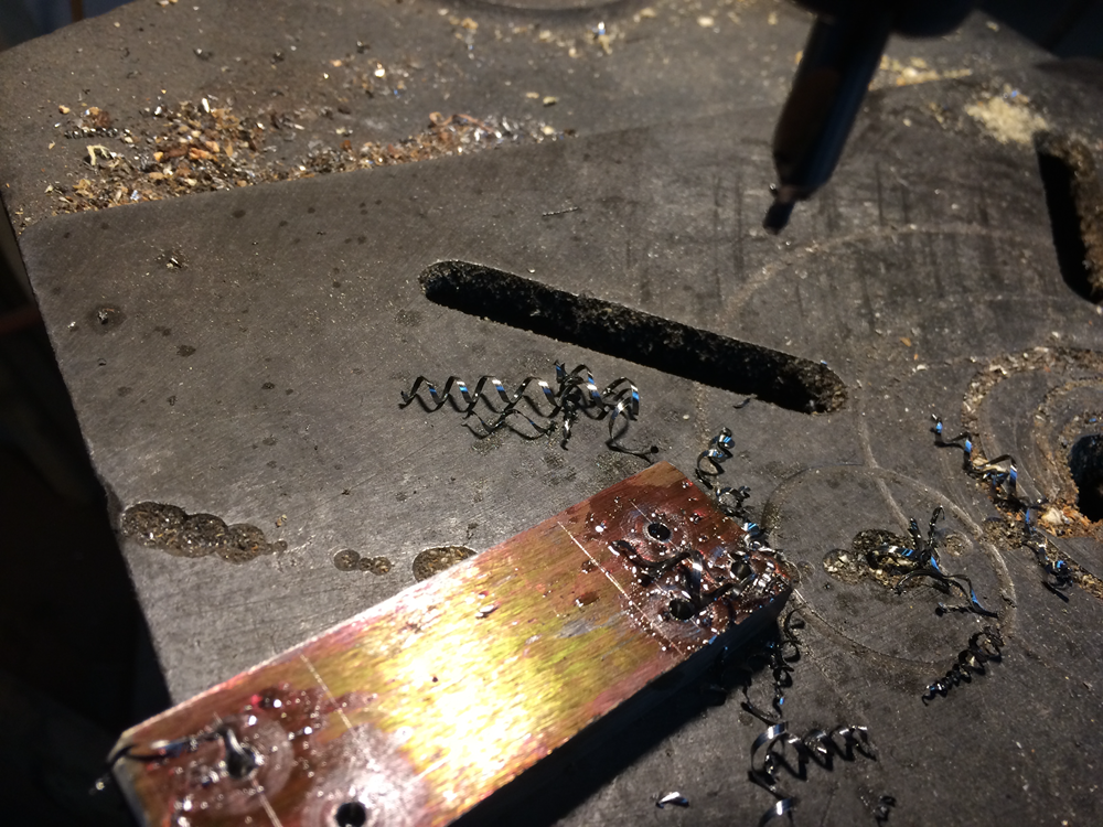
3. Drill the hole locations with center drill and follow with correct sizes per drawing and, if bar is oversized, saw as required.
Forming the rods:

- To drill the cotter pin holes at the end of the rods first make a drill guide from a ¼-20 nut (preferably square).
- With a ¼” bit drill out the threads.
- With a .08” dia. bit drill a hole through one side of the nut.

2. Insert the rod end in the nut and drill through the rod.

- To bend the rod end:
- Insert the drilled end in a vice.
- With one hand apply light pressure on the long end and bend to 90° by hitting it close to vise with a hammer.
Material suppliers:
The following are the suppliers I have used and found satisfactory. Obviously there are others.
- Stainless Steel rod and bar:
- OnlineMetals.com https://www.onlinemetals.com
- Metals Depot https://www.metalsdepot.com
- Washers and hardware:
- Bolt Depot https://www.boltdepot.com
- Cable and related hardware:
- Flanders Co. http://www.flandersco.com