Mostly stuff they don’t have in the manuals RON GARNER 2015© ALL RIGHTS RESERVED
Click any image to start a slideshow.
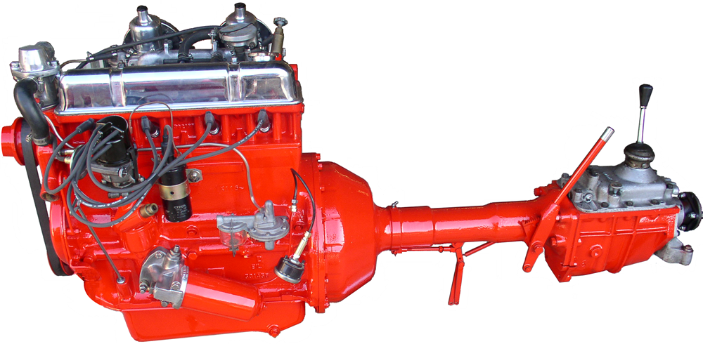
I’m not an engine guy, really don’t particularly like putting engines together, but I have had to build a lot of TRs, Ford Kents, Matchless and JAPs over the years.The TR is unique despite it reputation as an agricultural version of a boat anchor. The designers took pains to make it repairable by part replacement rather than reliance on sophisticated machine shop availability. If your +4 throws a rod in Timbuktu you can have Uncle Melvyn send you new bearings, a rod, a new wet sleeve and with a few basic spanners you will be back on the road again in no time.

Taking it apart
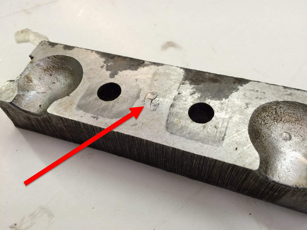
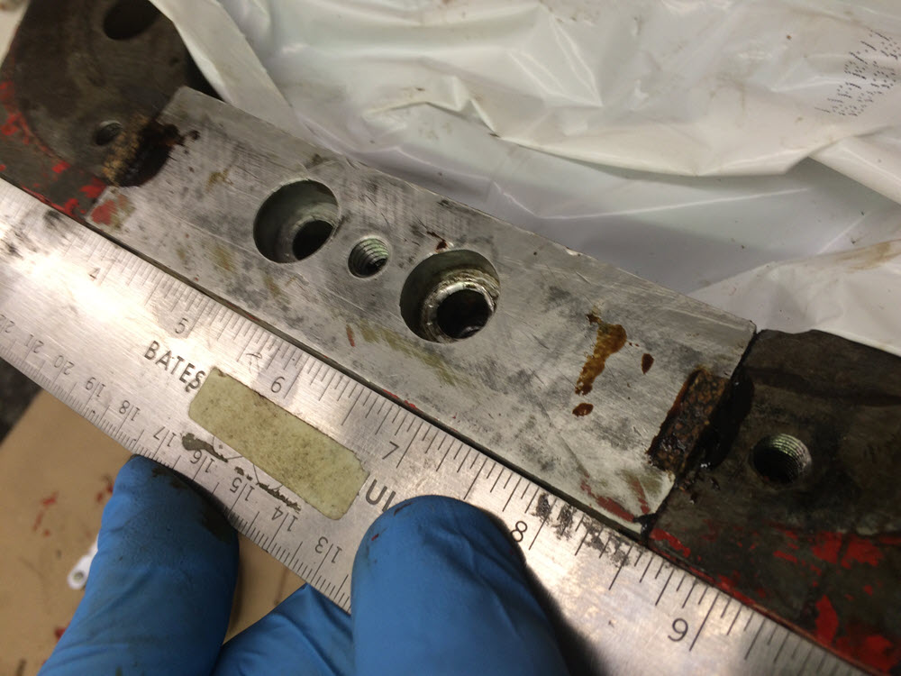
The engine shown in most of the following is from a 1964 +4. It was previously rebuilt by someone unfamiliar with the engine. How can I tell? See below. Prying the cam bearing or rear main seal does not work. Vice grips and pipe wrenches should not be used to remove head studs. Using screws correct for the depth of the hole should be obvious.

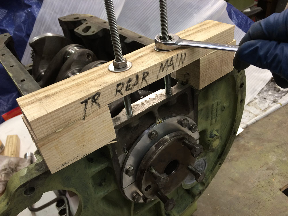
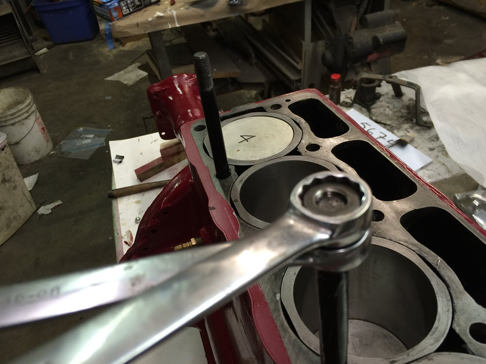
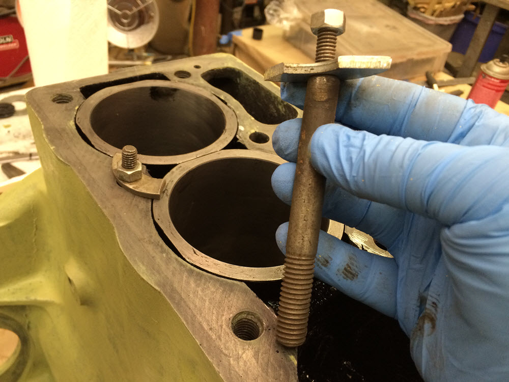
It takes but a few minutes to make a tool from some ash scraps and 5/16″-18 threaded rod to properly withdraw the front and rear main bearing caps. A similar tool will pull the cam to withdraw the front bearing. Studs can be installed or removed without damage by tightening two nuts on the end and turning with opposing pressure on a pair of wrenches. The only way to make sure a screw fits a hole is to check fit it without the mating part. Holes collect crud and even boiling does not always get it out. Chasing the holes, that is cleaning them by loosely threading a tap in, is a particularly good idea if the engine has be previously “rebuilt”. If a proper tap is not available a few hack-saw cuts across the threads of an old stud will make a reasonable facsimile.

Head studs and nuts There was a time when I was stripping the head nuts rather regularly when tightening to the specified torque. I assumed that the nuts failed because they were being reused or were poorly made reproductions. I sourced and used Grade 10 full nuts and even then I managed to strip one or two with every assembly. Finally I did some research and found that the 100+ foot pounds torque was specified for “clean and dry” nuts and studs. I typically oiled or applied Loctite to the threads. Bad idea. Since I stopped lubricating the nuts I have not had any problems. “Clean and Dry”; keep it in mind.
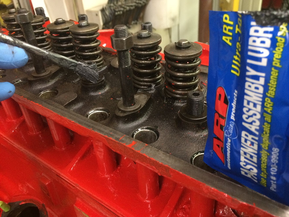
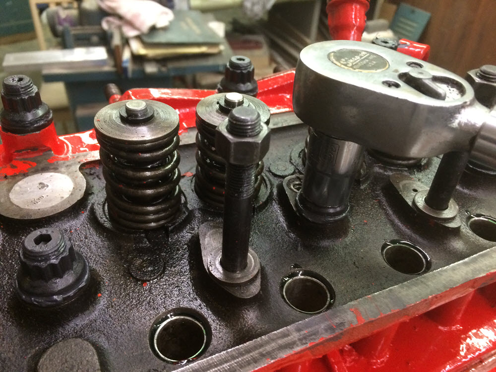
ARP head studs On a recent rebuild I used an ARP brand stud kit. It is overkill but, like a belt with suspenders, it can’t hurt. ARP specifies a lubricant when tightening.
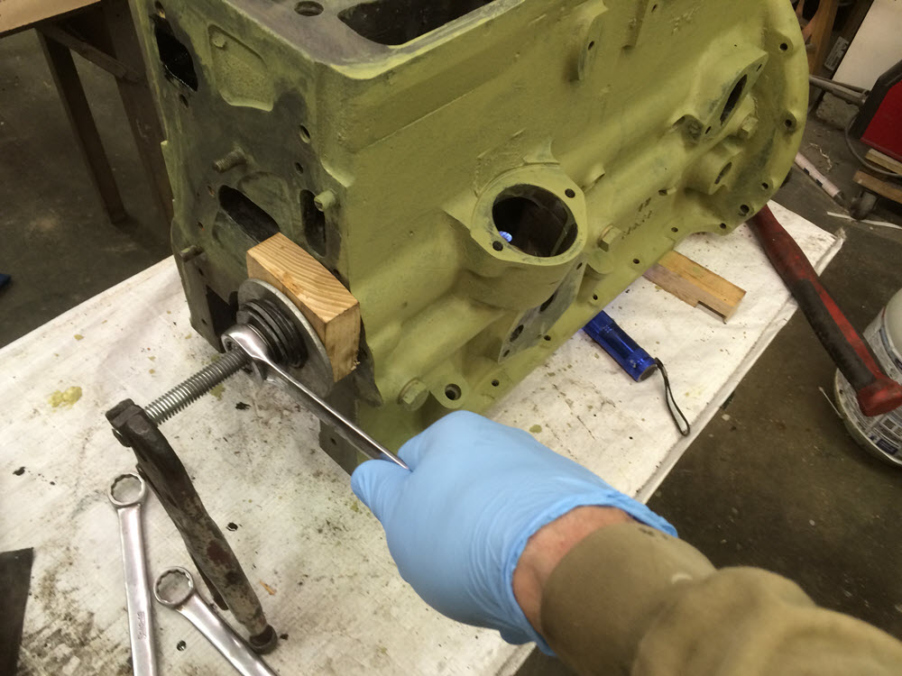
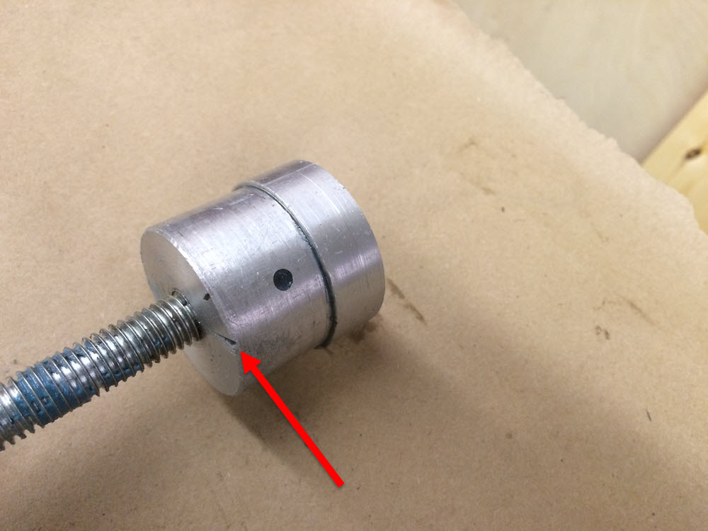
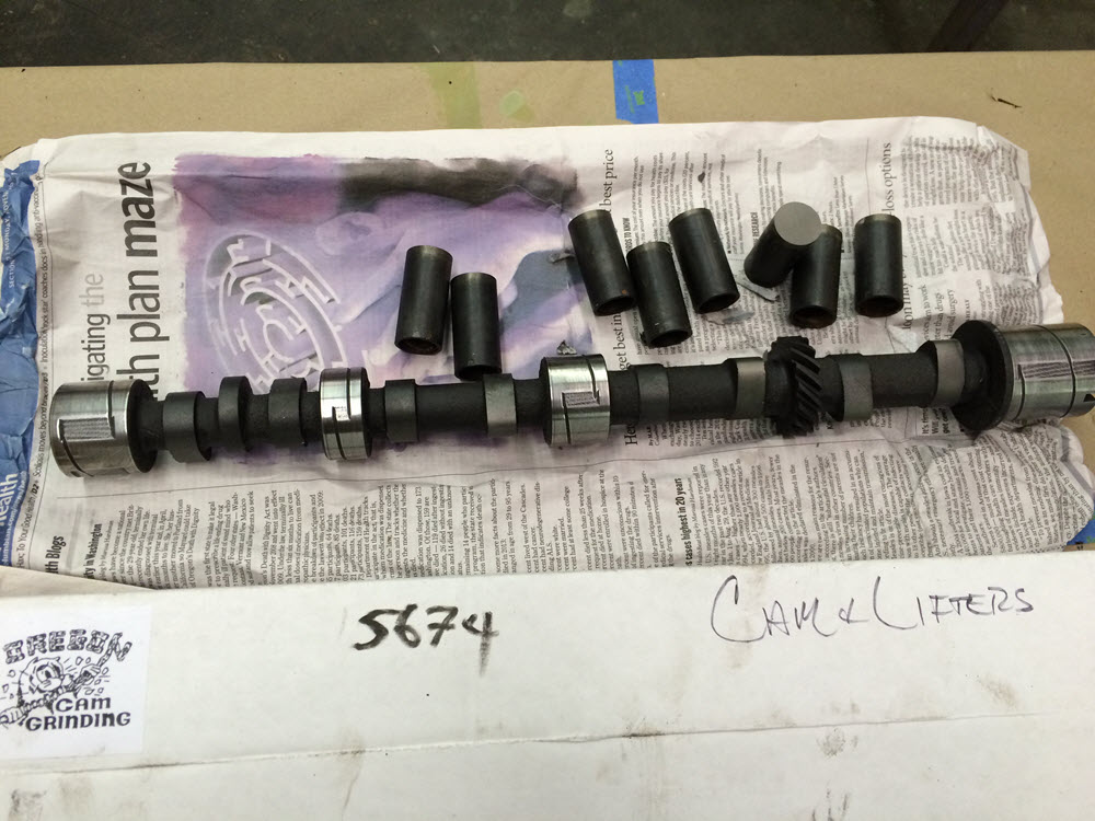
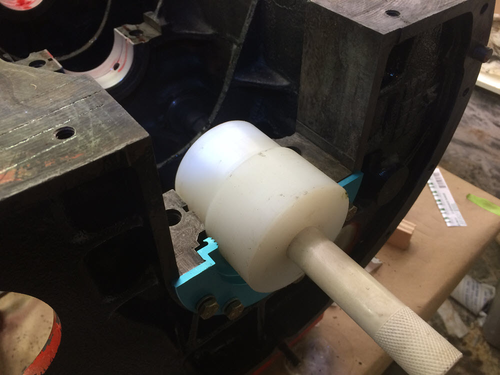
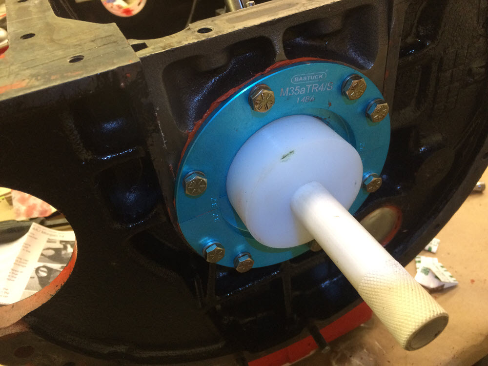
Remove and Replace Cam Bearings. Expect low oil pressure if you do not replace the cam bearings. I have a simple tool for removing and replacing cam bearings. It consists of a length of 1/2″-13 threaded rod, a block of wood to center the rod in the front cam bearing hole, and a stepped piece of aluminum to support the bearing.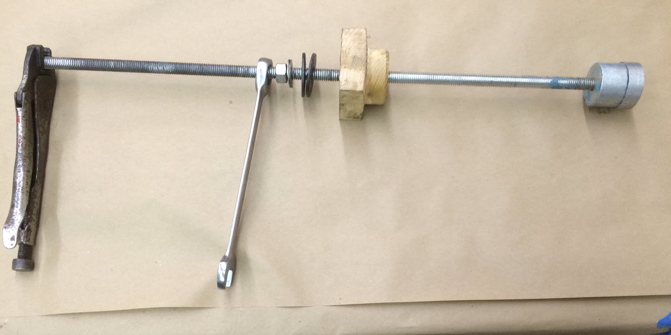
The support has a minor diameter that is a slip fit inside the bearing and a major diameter that is a slip fit in the hole where the bearing fits. It is tapped full length for the 12″-13 rod. Installed in the block as shown a vice grip prevents the rod from turning while a ratchet wrench tightens a nut to pull an old bearing out or a new bearing in. I do the rear most bearing first and then tip the block on end to do the next two. Note: everything gets liberally coated with assembly oil before and during installation.
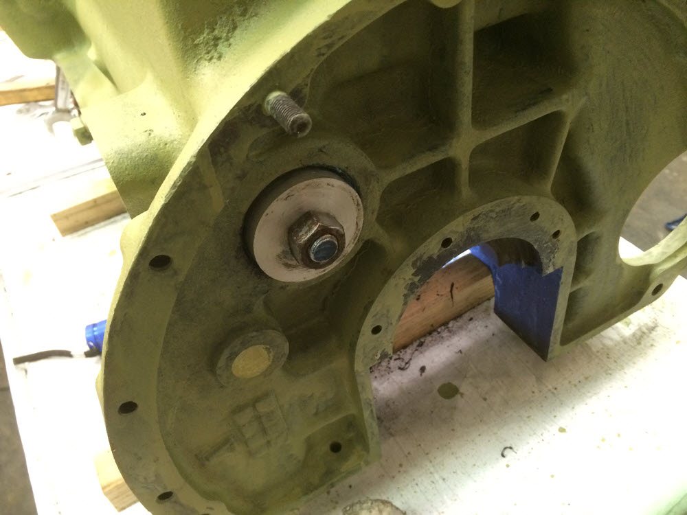
The hardest part of installing cam bearings is correctly lining up the holes in the bearing with the holes in the block where the dog-point set screws fit. Any interference between the dog-point and the bearing will push the bearing against the cam. In the worst case the cam will not turn at all. Always put the cam wheel on loosely and rotate the cam by hand to verify that there is no resistance to turning. There is a file mark on my stepped aluminum bearing support to line up with the hole in the bearing and then with the hole in the block before pulling it into place. If the holes do not line up perfectly, it is not a big deal to continue pulling the new bearing all the way through to start over.
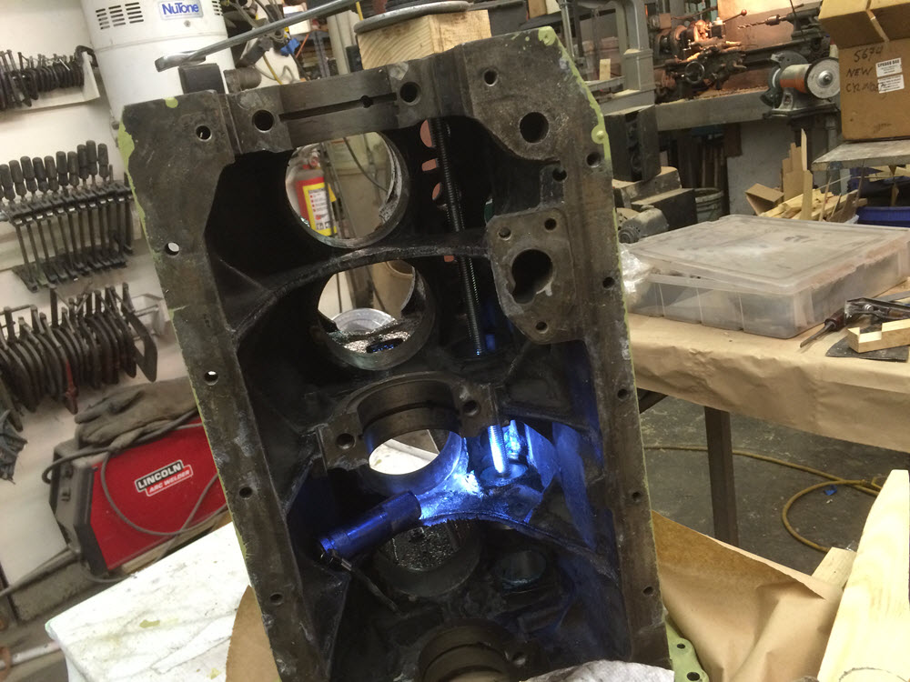
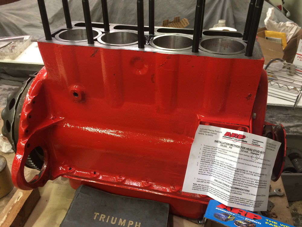
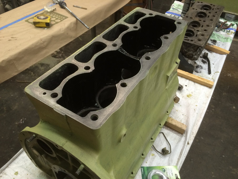
 Install new Wet Liners. If the wear is minimal and the ring clearances within tolerance I will simply hone the existing liners, rotate them 90 degrees and reinstall with new rings. This engine was previously buggered leaving no choice but to either rebore or buy new piston/liner set. I chose the new set. Before installing I soda blasted the block inside and out, treated it with OSPHO conversion coating, brushed etching prime on the exterior and the interior wet area and finally brushed Imron on the interior wet area.
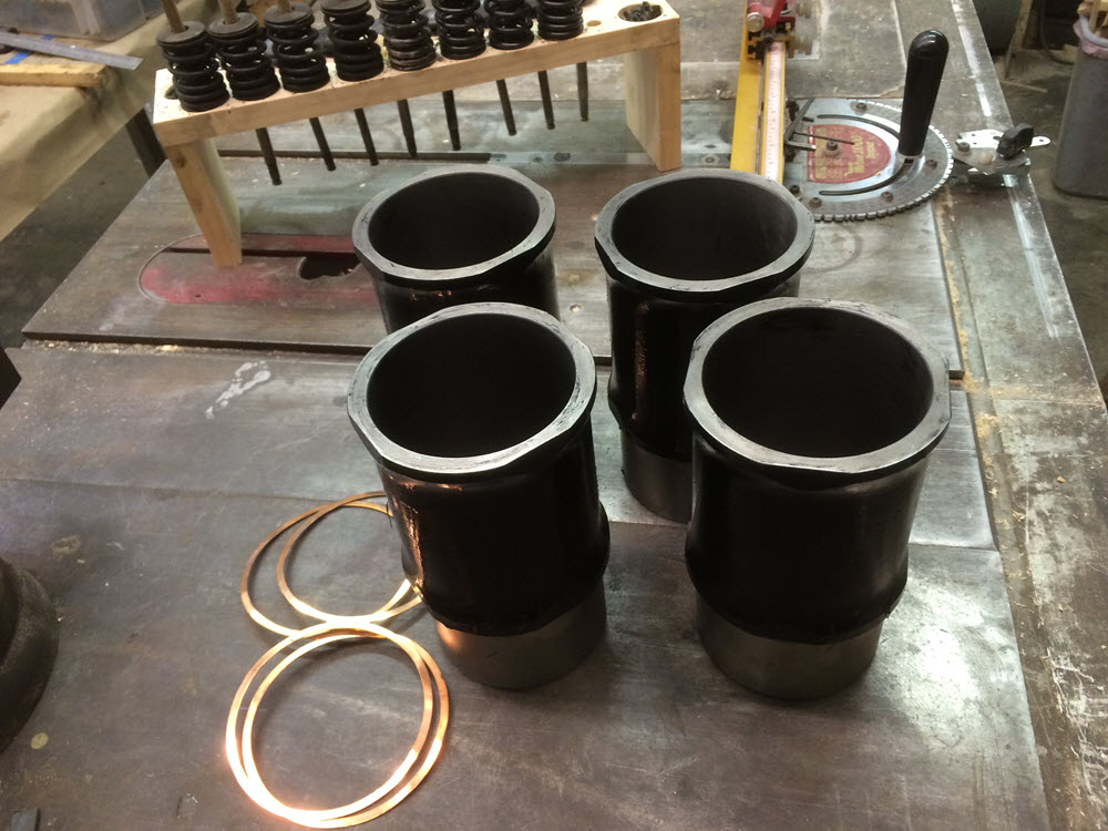
A high quality sealant is brushed under and over the figure 8 gaskets. I have two homemade retainers to prevent the liners from shifting during the installation of the pistons. To make the retainers I cut an old stud (or maybe a long bolt with the right thread, it was a long time ago so I’m not certain) drilled the cut end and brazed in a length of 5/16″ threaded rod. A segment of a large diameter washer completes the retainer and bears on the top of two adjacent liners.
There is more than one way to do most jobs. Installing pistons requires a ring compressor. Installing the pistons from the top (as I did with this engine) can be challanging because there is no chamfer on the cylinder. Installing the pistons into the bottom of the liners before they are in the block is easier. The Crankshaft can be installed before or after. Sometimes I do it one way sometimes another.
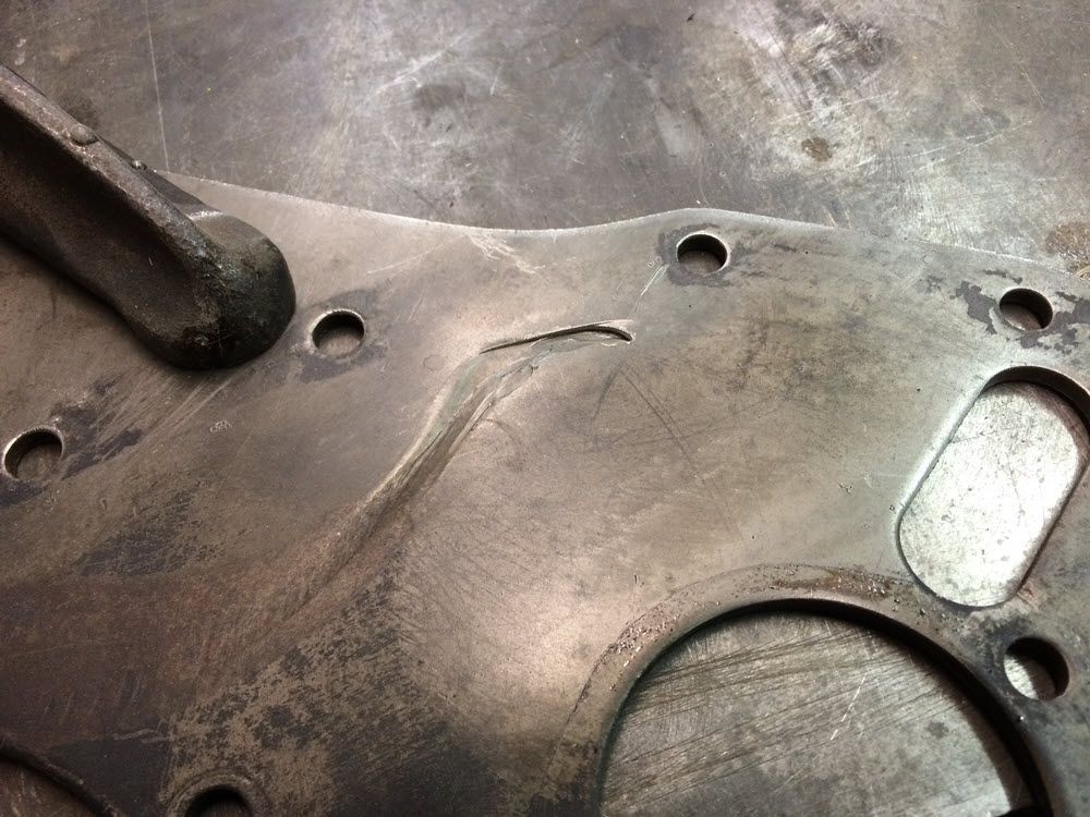
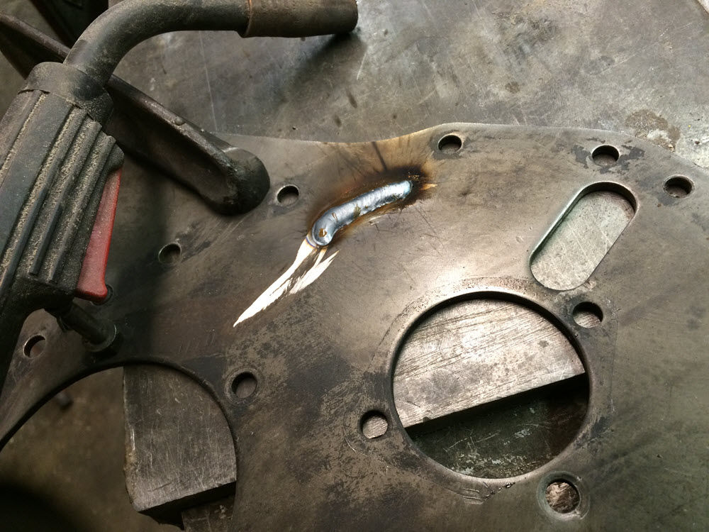
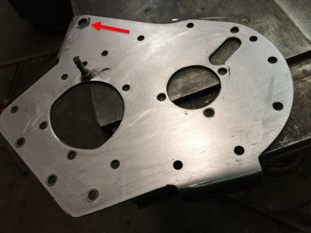
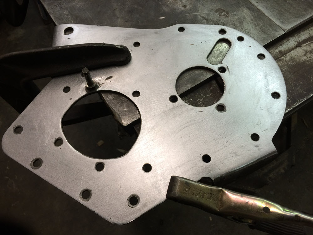
Front Mounting Plate Any TR engine with enough miles on it to warrant rebuild will have a significant groove worn into the front mounting plate under the timing chain tension spring. Ages ago I tried filling the groove with weld using Oxy/Acetylene. It was a disaster. Front mounting plates are unique for Morgans, Warp or otherwise make one unusable and it is not easy to find another so after that one bad experience I played very conservative for thirty years and just smoothed the sharp edges of the groove and put it all back together. The groove on this engine was more than halfway through the plate so I revisited the welding option. This time I used MIG and it worked beautifully. The plate was firmly clamped to the iron base of my table saw for support and heat sinking. It worked so well in fact, that I also welded the depression and elongated hole at the generator mount.
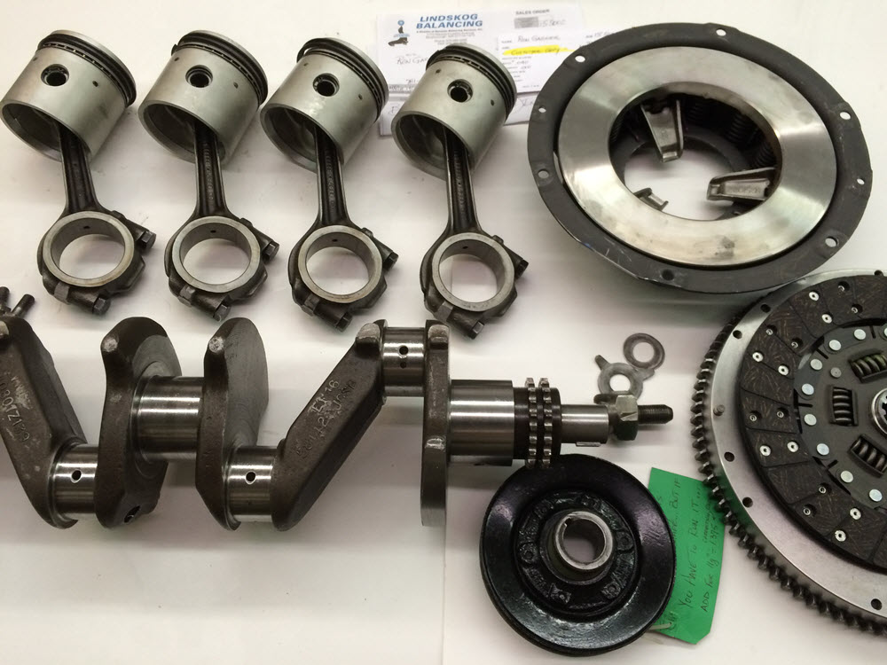
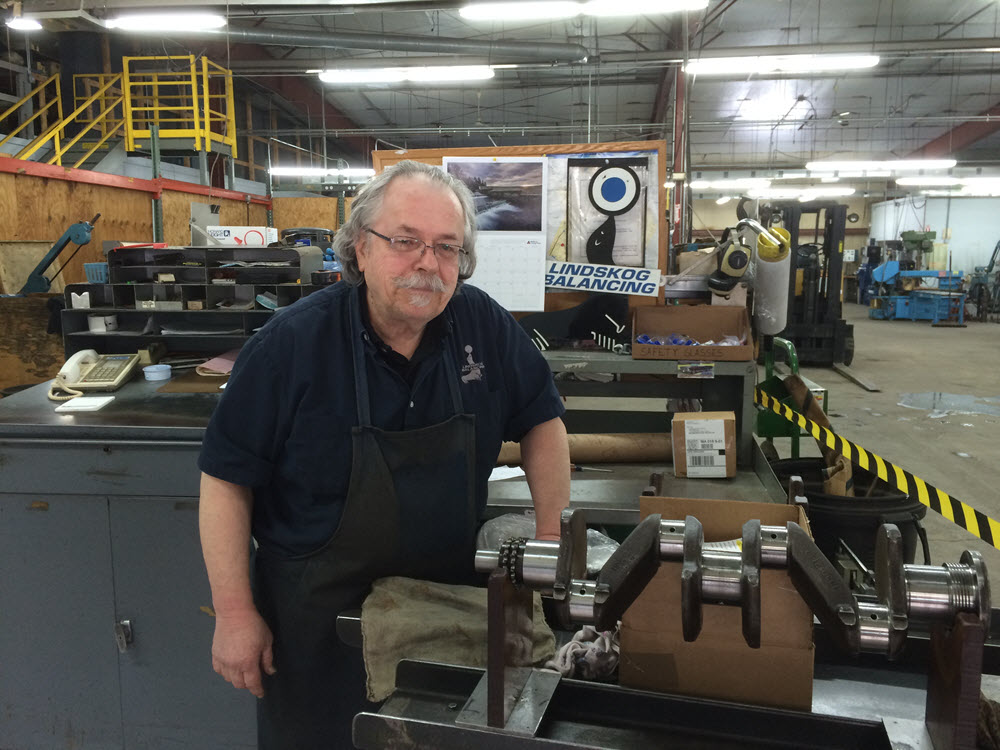
Rotating and Reciprocating Parts I’m not a racer or performance nut. If I wanted a car that had the power and performance of a modern sports car I would buy a modern sports car. I drive old Morgans and, with a few exceptions, I am content with rebuilding them to the original standard. Balancing is one of those things that I always did when I could pass the charge on to a customer but for my own cars I usually left things as original. The plans for this car include some long distance touring far from home so I used a belt and suspenders approach that included replacing many parts that were simply marginal and also a complete balancing of the rotating and reciprocating parts. Everything that goes round and round was sent to Lindskog Balancing in Boxborough MA.
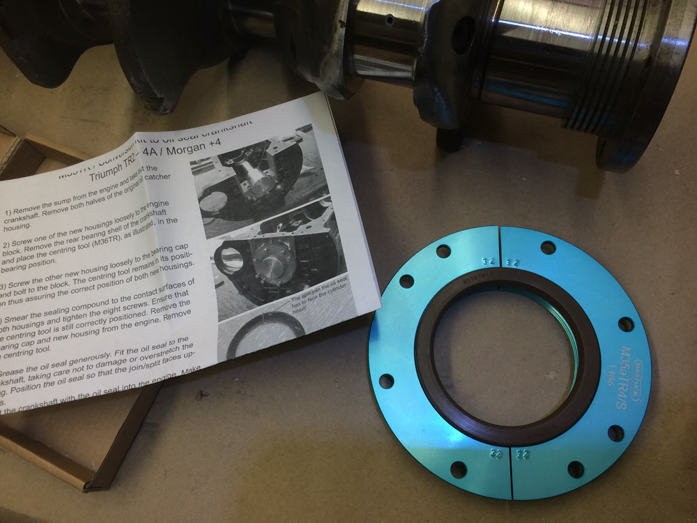
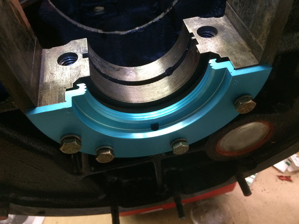
Rear Main Seal If the engine leaks through the rear main it is because something else is wrong. The seal is a labyrinth design that has no contact so it will never wear a groove in the crankshaft. Converting to one of the “new and improved” lip seal options is an expensive step backwards. The factory workshop manual describes using a special mandrel to center the seal. I don’t have one. It was after I completed this job that I noticed that they are available through Moss Motors. Even though I swear this is my last Morgan I would have bought a mandrel had I known. My alternative process: 1. install the main shell bearings in the block, 2. apply gasket sealer on the mounting faces of the seal halves and loosely fasten them to the block and bearing cap. 3. Oil the shell bearings. 4. Place the crankshaft in the block. 5. insert the shell bearing in the rear main cap. 6. Assemble and torque the rear main cap. 7. Rotate the crank by hand to verify fit. 8. With a small drift, lightly tap the seal halves together around the crankshaft. 9. Use a torque wrench to tighten the seal fasteners. 10. Continue with assembly.
Better idea: buy the mandrel.
UPDATE: March 2018
I had to revisit this engine after a head gasket failure while on tour in Italy. It was the first ever head gasket failure that I have had and I blame it on the new composition head gasket that I used in the first rebuild. From now on I only use the traditional copper head gaskets. Uncle Melvyn sent me a new (copper) gasket and I swapped it out in a parking lot in Tuscany. A field repair will get you home; it is not what you rely on for another tour far from home.

Composition gasket: caveat emptor!
More on that rear seal:
After umpteen engines I finally decided to try one of the new rear seal options. I chose the BPNW seal conversion (part number 060862UPR) because it does not require machining the crank and is therefore reversible. Also the seal contacts right at the extreme rear of the crank where, should wear happen, it would not have any effect if one wanted to go back to the original set up. As of this writing the engine is installed and running. There is no leaking and that is good but it hasn’t gone many miles so the jury is out as to whether it is worth the $200 investment. And… I took my own advice and bought the mandrel!
CAUTION>>>>>>>>>> when using this type seal be absolutely certain that the four flywheel bolts DO NOT protrude out the back of the flywheel. Any protrusion will chew up the seal (ask me how I know).
2024 update: I have installed this seal on four engines now. The jury is still out. My own DHC has about 10K miles and I am seeing a bit of a puddle under it while FAINE, the four seater I sold to my neighbor is stll dry. Go figure….

Ages ago I remember John Sheally recommended trimming the sides of the rear seal flush with the sides of the bearing cap. The stock design, with the seal overlapping the bearing cap makes it impossible to withdraw the cap with the flywheel attached. In other words, the engine must come out to service the main bearings. When assembling engines for customers thirty years ago I would trim the seals. Seems silly now. If I have a bearing failure I want the engine out, pure and simple. No trimmed seals thank you.
Rear Main Bearing Cap Packing the rear bearing cap is a rather bizarre operation if you think about it. The manual says to cut the felt strips into shorter bits, soak them in gasket goo, and pack them in the hole with a drift. If that is what the manufacturer says to do; that is what I do. The people that designed and built the engine are smarter than I am. It is just that I cannot imagine this being done in production on the assembly line when the engine was originally built. “What’s your job mate? I pack the wad-o-wool…”
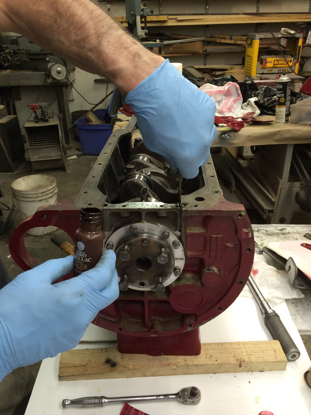

Also; The strip of felt that comes in some rebuild kits are not long enough. I have blocks of felt that I use to make hub seals for trikes and cut extra strips from that. Any cotton rag will probably work as well provided ample gasket cement is used.
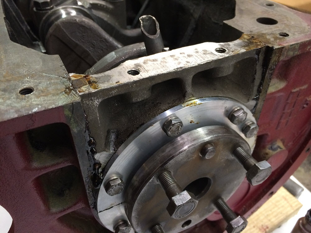
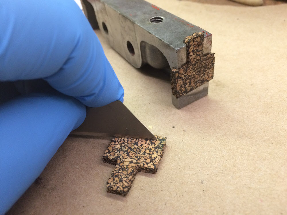
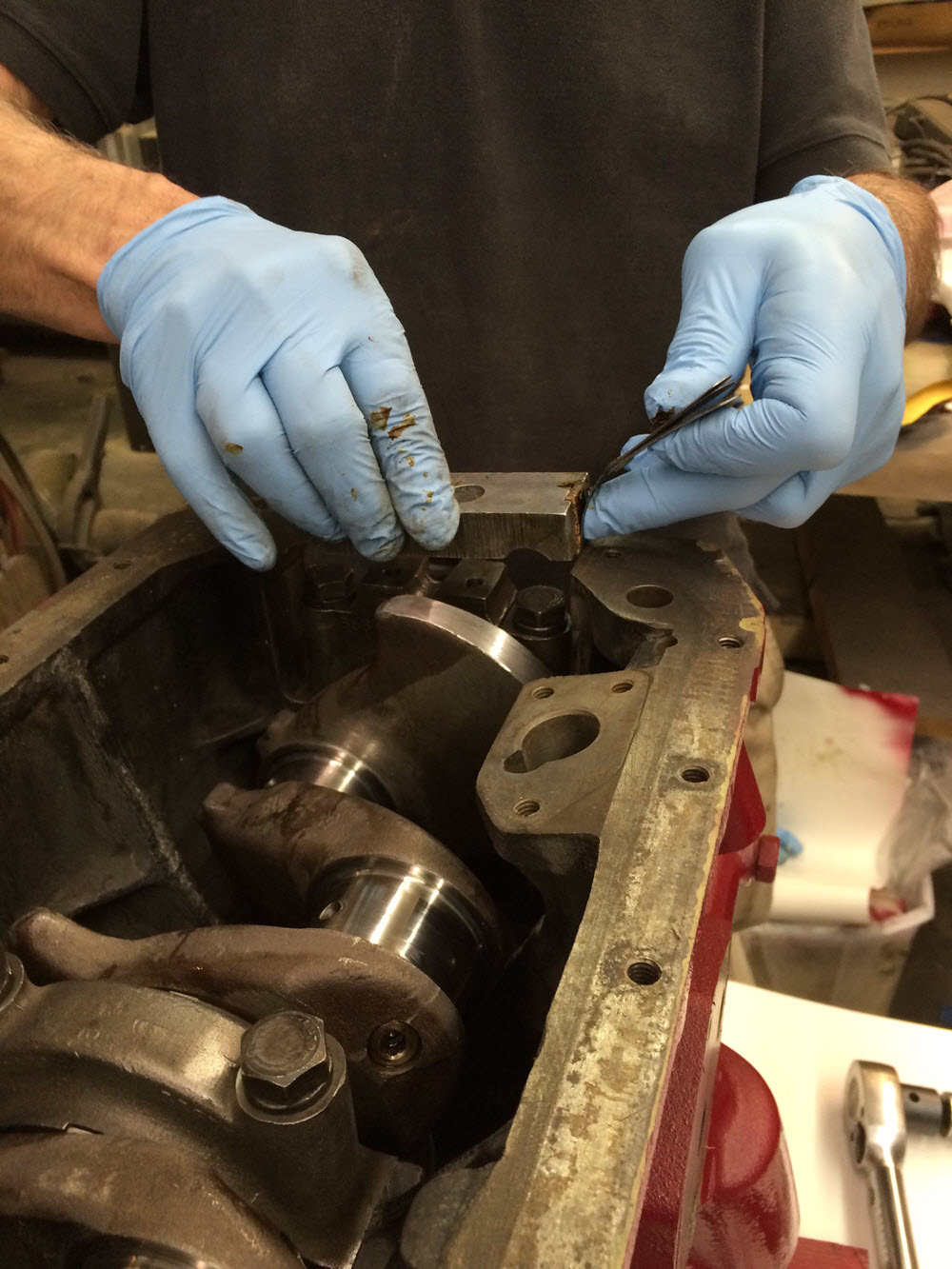
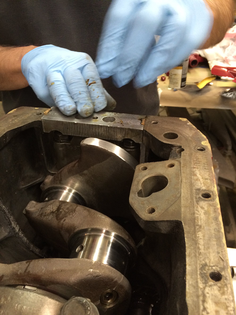
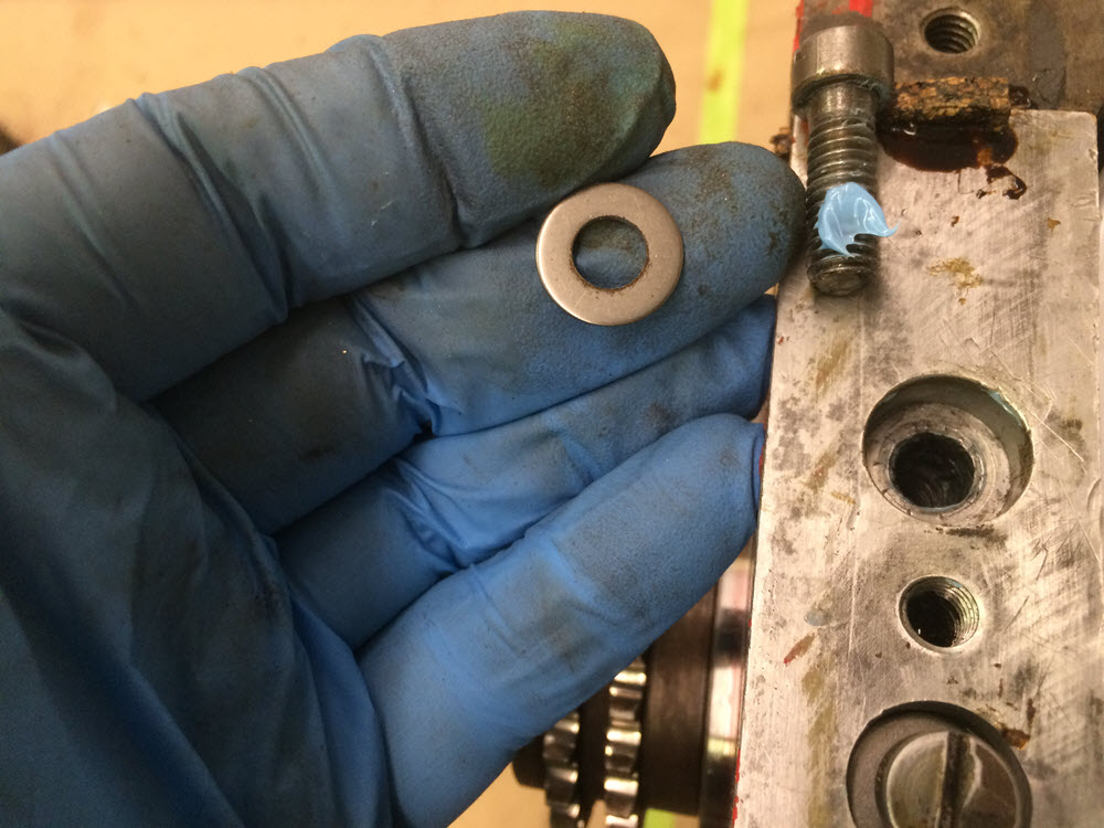
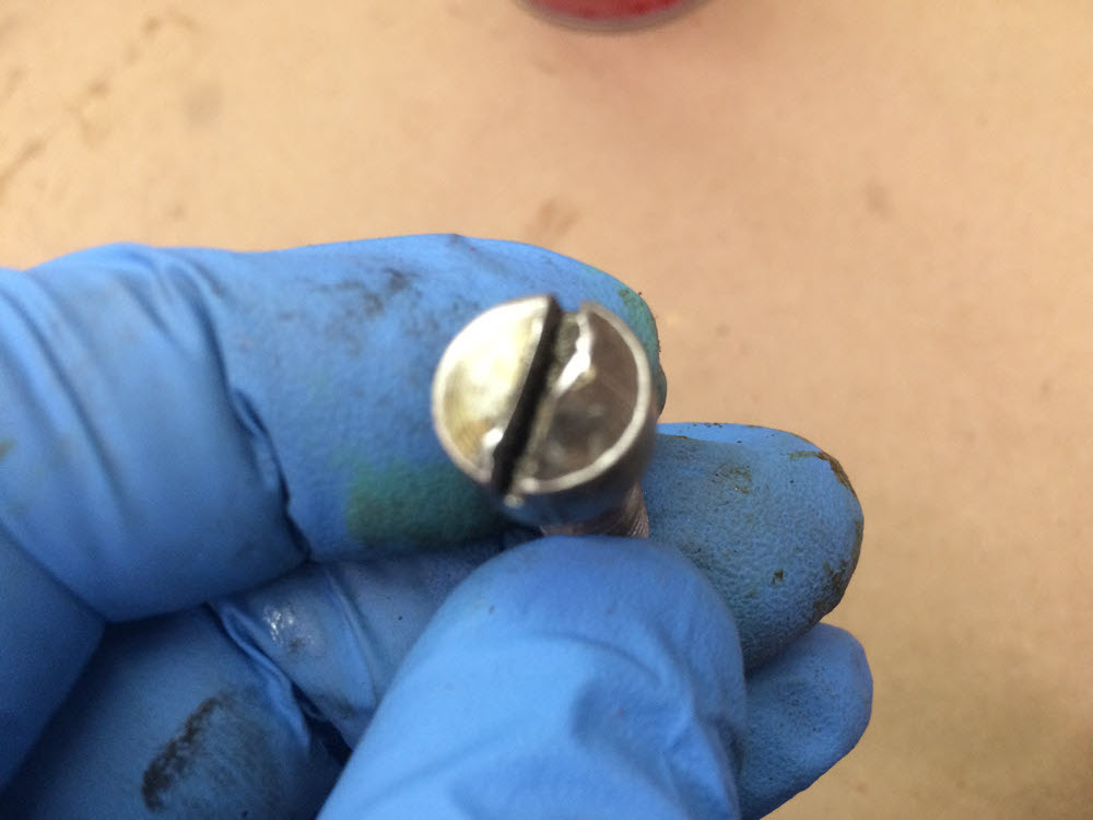
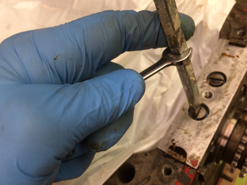
Front sealing block I destroyed more than a few T shaped cork gaskets in my time. Finally I learned to trim them to be a snug fit in the end recesses of the aluminum block, apply gasket goo, and use a thin feeler gauge on one side to compress and slide them into place. The factory manual says to align the front of the alloy piece with the front face of the block. What the manual does not tell you is that the location of the alloy block is dependent on the location of the front main bearing cap. Be certain to align the front main bearing cap with the front face of the block or the alloy block won’t. A washer under the cheese head screws helps and make sure the screwdriver is a snug fit in the slot.

Oil Pump Way back in 1973 my daily driver ’53 +4 had extremely low oil pressure. I rebuilt the Vanguard engine (my first experience with the TR family of engines) and it still had virtually no oil pressure. I suspected the oil pump. To test the pump I flattened the end of a long steel rod, removed the distributor tower and inserted the rod down the hole until I could feel the flattened end engage in the oil pump. With an electric drill I spun the rod. Nothing happened. Ah! the pump must be bad. Then I reversed the drill. Believe me these pumps can really move oil. Try the experiment yourself sometime but be sure you are wearing disposable clothes. Eventually, after the second rebuild, I found that the pressure relief spring in the oil filter body was broken. The moral to that particular story is that you should look in the oil filter casting assembly and verify that the shiny ball is tight against its seat. The pressure relief is factory set to 75 PSI. Note: it is a pressure relief valve, it cannot be used to increase the oil pressure on an other wise worn engine.
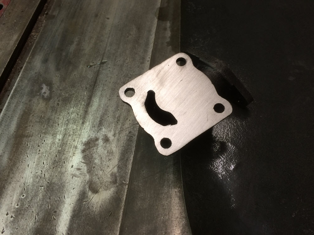
The factory manual gives maximum clearances for the rotor and end float.

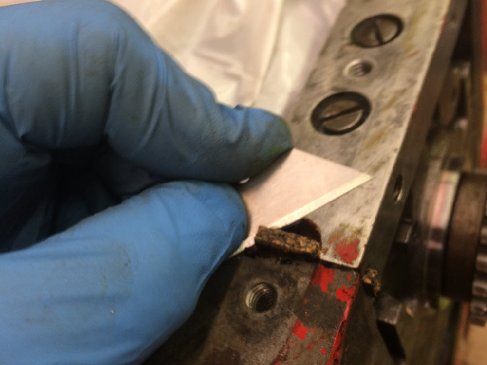
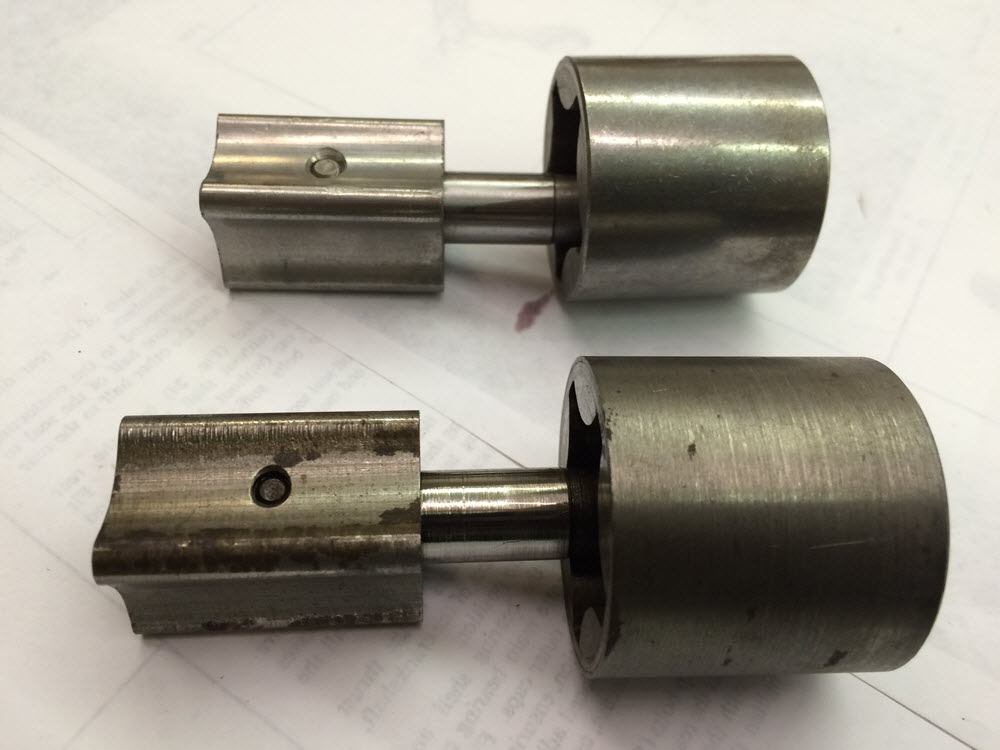
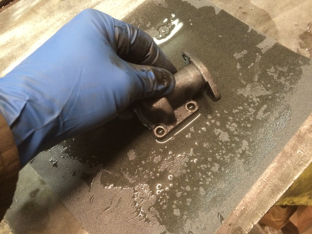
Complete new pumps or new rotor sets are available. In my experience, even old worn pumps work fine, however, I recently replaced the rotor set on another engine and observed the hot idle pressure change from near zero with the old rotor to about 20psi. To my mind, that made the change worth doing. I typically lap the pump end cap to remove the wear grooves. 220 wet-or-dry sandpaper on a flat steel surface works fine. If you are reusing the old rotor set the same technique can be used on the body of the pump to correct excessive end float . For this engine I bought a new rotor set because it was fairly cheap and the old rotor was pretty bad. Lastly; always stick a screwdriver down the pump end and make sure it turns before you install it in the engine.
Closing comment: Have a factory workshop manual handy before, during and after engine assembly. They are readily available from various sources and there are links for down-loading as well.
A few afterthoughts (2022)
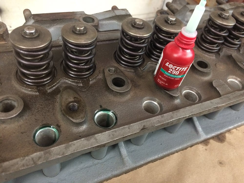
Cylinder Heads: Occasionally the pushrod tubes leak. This particularly true if the head has been cleaned by boiling. They are a bugger to reseal. I’ve tried swedging, and various silicones without success. The only positive results have been with Permatex Loctite PENETRATING or Wicking grade thread sealers. When the head is off and clean, dribble the Loctite around the top of the pushrod tube. If there is any opening large enough for oil to penetrate the Loctite will fill it; at least that is the theory. I’ve done it on a few heads and they did not leak. I have no idea how long it lasts but it can’t hurt. Well, actually, there is a way it can. Read on. DO NOT DO THIS ON AN ASSEMBLED ENGINE: If there is a mistake to make I will find it. I did this once on a newly assembled engine. The Loctite dribbled down the hole and fused the lifters in place. After removing the head several lifters were damaged trying to remove them. The end result was new set of lifters and a lesson learned.
Leaky front seal
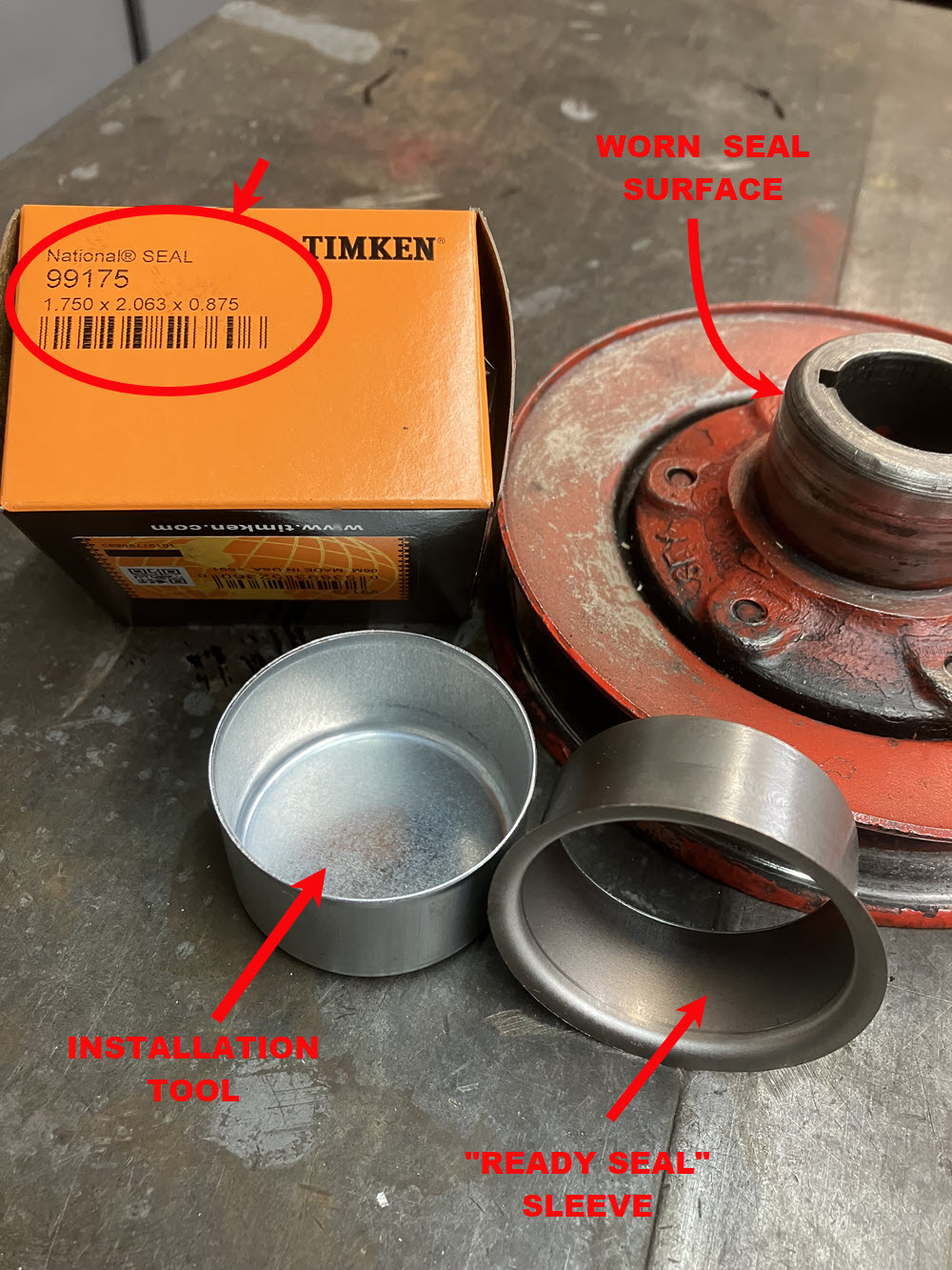
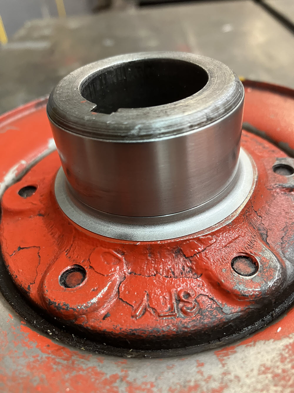
The timing cover seal will leak if the pulley hub is worn (and it usually is). This is a perfect example of the engineer’s maxim that the soft will wear the hard. The rubber seal holds contaminants in the oil and, over time, cuts a groove in the hub shaft. Redi Sleeves by Timken are a solution. They are very thin stainless steel shells that push on over the worn shaft and provide a new seal surface. They are available from any bearing supply store, on-line, and from Moss Motors (at higher cost).
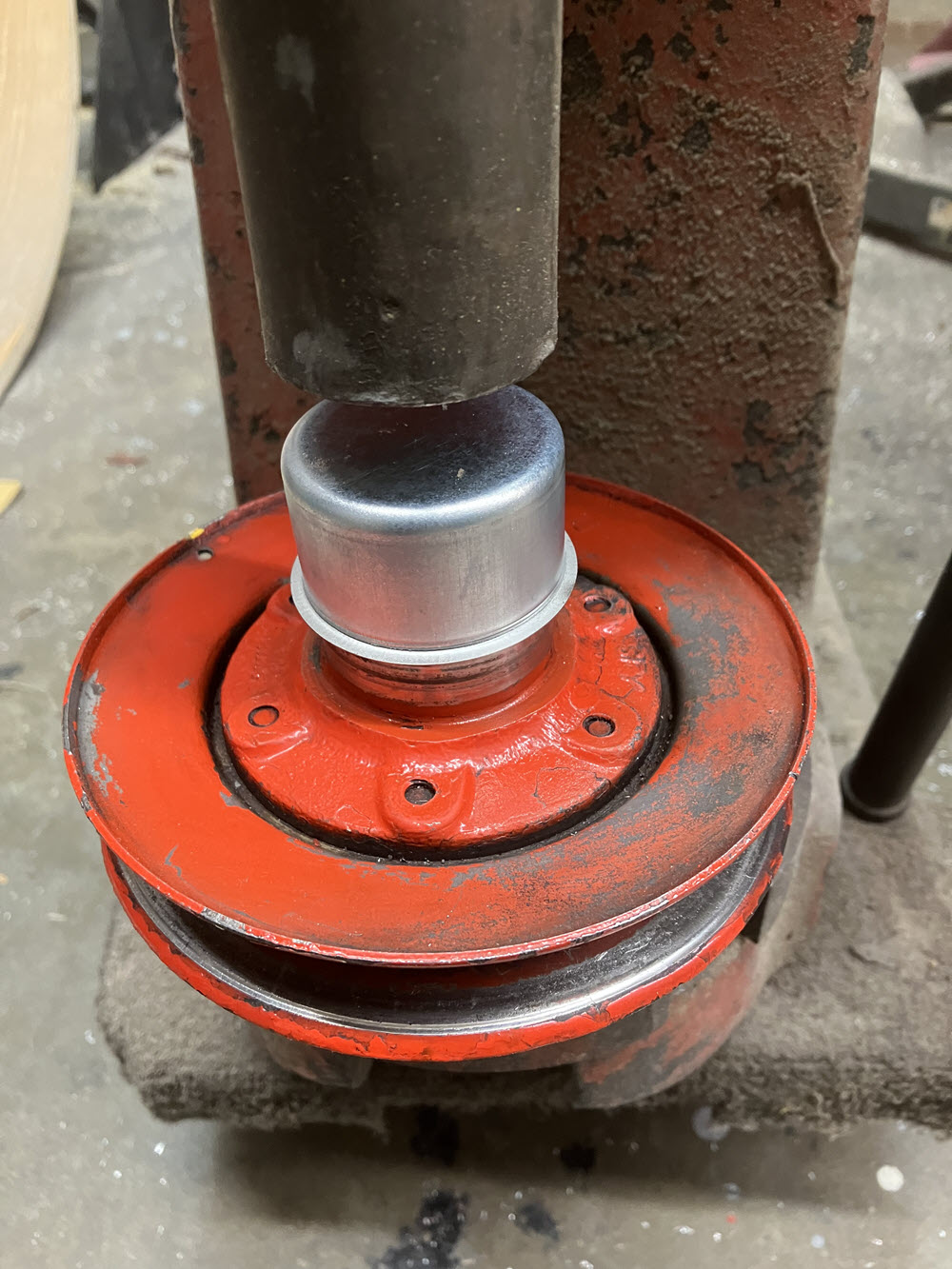
The sleeve comes with a cup shaped installation tool. It can be installed with a press or tapped on with a hammer. The sleeve has a lip that can be torn off but in this application it is left on.
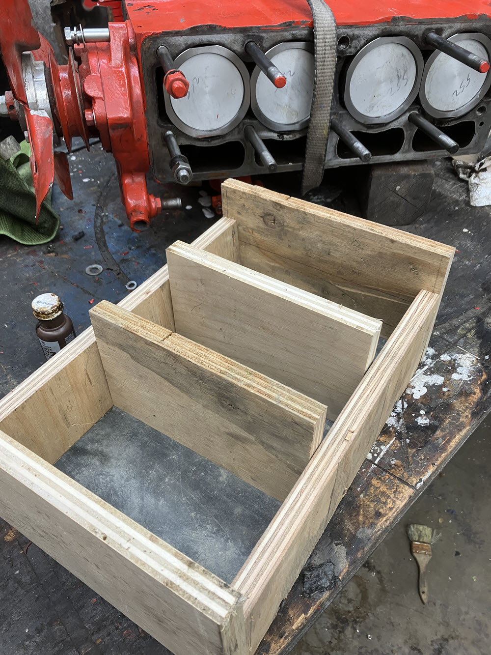
Not Every Rebuild Requires Head Stud Removal
But it is a pain to change bearings and install a crankshaft with the block on its side. I made a box of 3/4″ plywood approximately 14″x8″ with a depth of 5″ to support the block while doing bottom end work.